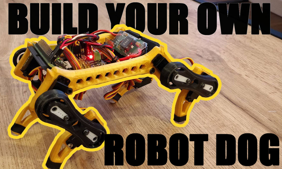
Follow this tutorial to start building your Quadruped Robot right now with Edog Kits.
Edog is a fully 3D-printable robot that’s not only straightforward to assemble but also budget-friendly. Powered by the compact Raspberry Pi Zero, it’s versatile enough to support a variety of Linux distributions. Remarkably, Edog can command up to 16 servo motors at once, all while leaving the entire GPIO board free for any additional components you wish to integrate

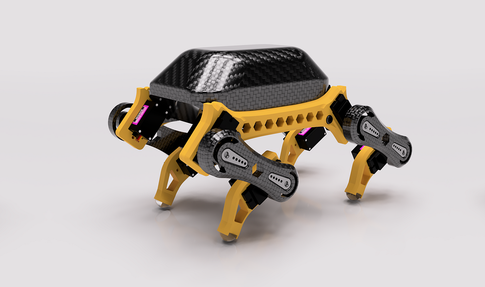
What are we building ?
We are building a quadruped robot, which naturally means it can walk. But that’s not all! This robot is powered by a Raspberry Pi Zero, enabling it to run a Linux OS, connect to any Wi-Fi network, and be controlled wirelessly. With this architecture, you’re free to code whatever you want using your favorite programming language. Additionally, you can integrate your own components and actuators via the Raspberry Pi’s GPIO or aditionnal servo motors.
https://www.youtube.com/watch?v=4XOQ5IJtXQM

Requirements
- 8 * MG90S (or SG90) Servo Moto
- 1 * Raspberry Pi Zero WH
- 1 * Driver Servo — PCA9685 16' canaux 12-bit pwm- I2C
- 1 * Power supply — HENGE 8A UBEC 5v
- 1 * 7V-25.5V Input for 2–6 Lipo
- 3D printed part (Available on eatsy)

Usefull link
3D Prints Files: edog.io
Official Github Repo: github.com/SolidMakers
Instagram: instagram.com/solidmakers_official
Hackaday: edog-mini-3d-printed-quadruped-robot
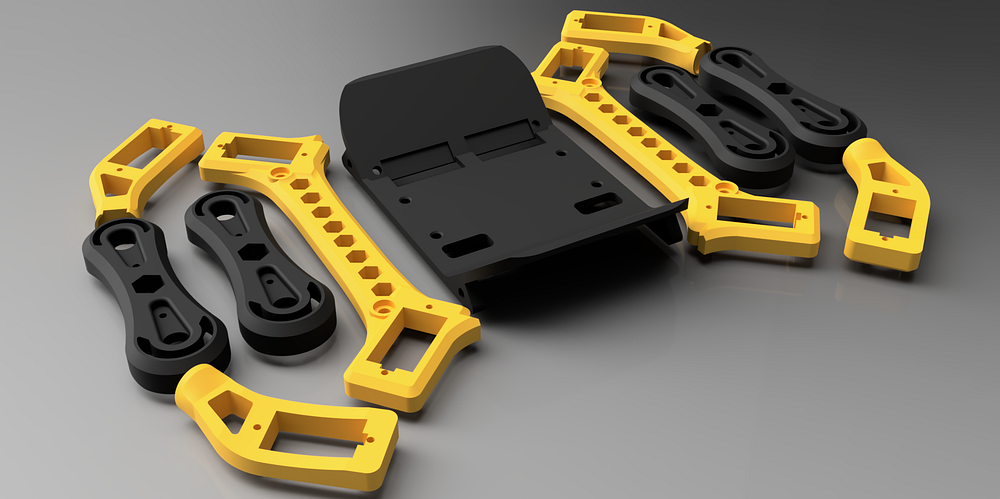
[Step 0] 3D Prints
The entire structure of the robot is fully 3D-printable. All parts are designed for easy printing and don’t require any supports. If you already own a 3D printer, you can access the STL files via this link.
https://edog.io/products/3d-printable-files-for-edog-quadruped-robot
If you don’t have a 3D printer, you can order the parts in your desired color from **Product will be add to the edog.io soon**
[Step 1] Install the electronic components
Secure the Raspberry Pi and the Servo Driver to the frame using M3 screws. You can directly screw into the specially designed plastic frame, be careful not to over-tighten.
Fix the Power supply to the frame using double-sided tape or glue
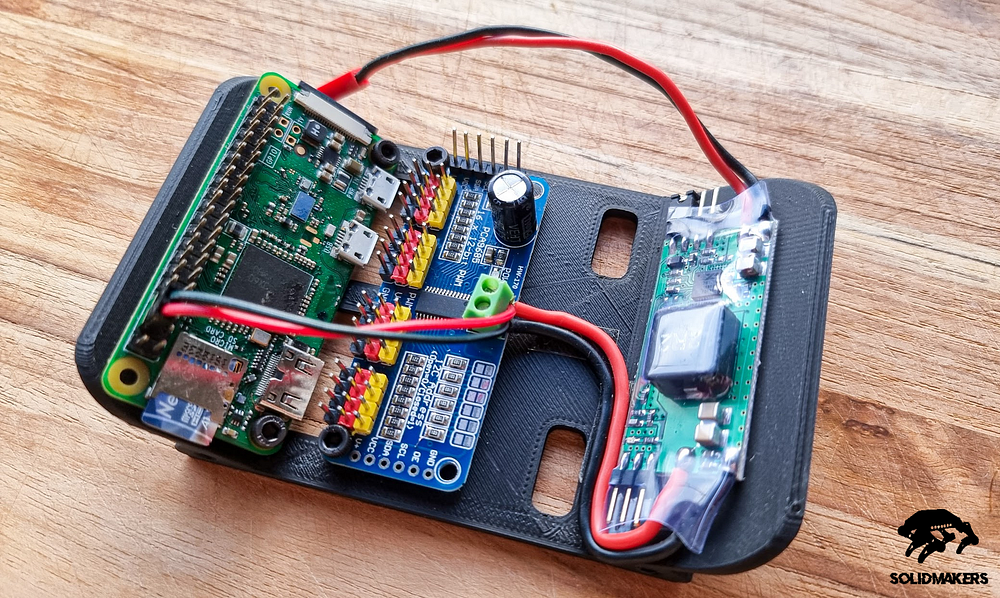
The power supply’s role is to transform the battery’s voltage into a consistent 5V, enabling us to power both the Raspberry Pi and the servos.
Follow the wiring diagram shown in the image below, ensuring you don’t reverse the voltage.

Note that there’s no need to power a Raspberry Pi via the USB cable; you can instead directly connect to one of the 5V and GND pins.
[Step 2] Prepare the SD Card
Now, let’s proceed with the preparation of an SD card for our robot. We will install the Raspberry Pi OS (based on Debian), and configure it to ensure that the robot automatically connects to your Wi-Fi network upon startup !
While you’re free to choose any Linux distribution compatible with the Pi Zero, for the purposes of this tutorial, we’ll be using the official Raspberry Pi OS with the Raspberry Pi Imager software. There are numerous tutorials and YouTube available that provide clear instructions on the installation process, here is a good one:
By tweaking a few files on its microSD card, you can set your Raspberry Pi for remote access without ever attaching a…www.tomshardware.com
- Download Raspberry Pi Imager and run it
- Select the default Raspberry Pi OS
- Select your sd card device
-
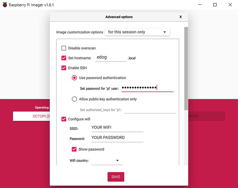
Important, in the ‘Advanced Options’:
- Setup a hostname for your robot
- Enable SSH and setup credentials you want
- Configure your wifi so the robot will automatically connect to it
Now, insert the SD card back to the Raspberry Pi.
Wait for the Pi to boot (first boot can be pretty long ~15min)
By now, you should be able to observe the Raspberry Pi establishing a connection to your home Wi-Fi network after boot. You sould be bale to connect to it using the hostname and credentials that were specified during the SD card configuration process
ssh username@hostname
[Step 3] Assemble the frame and Install Motors
Upon gaining SSH access, you are able to safely shut down the Raspberry Pi before disconnecting the power supply
sudo shutdown now
Attach both side plates to the frame using 4 * M3 15mm screws and bolts.
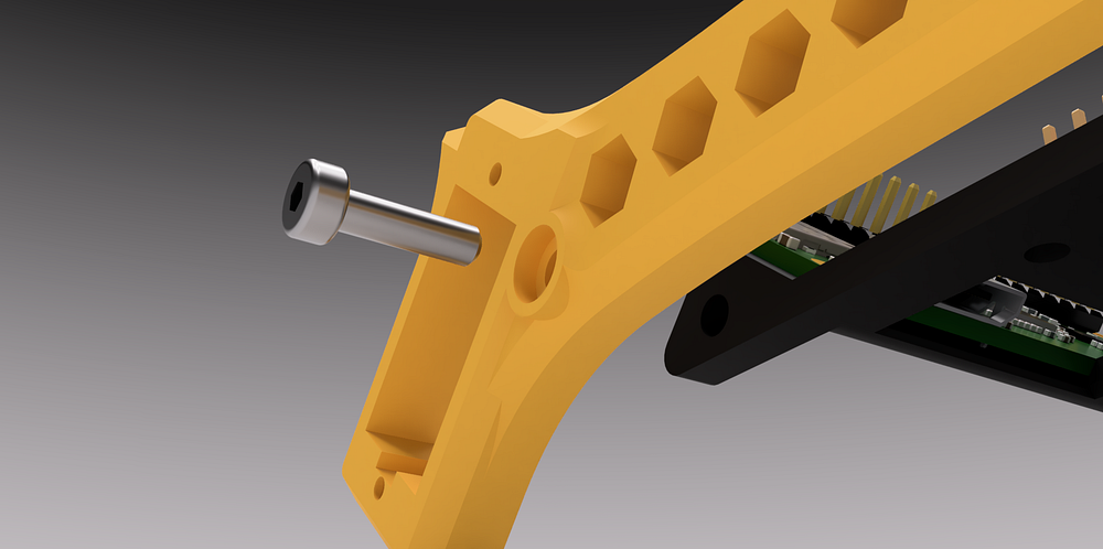
Insert the eight servo motors into the 3D-printed parts designated for them, as illustrated in the images below. Secure them using the screws provided with the motors.
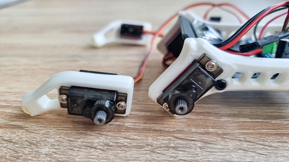
Do not mount the femur yet, we need to calibrate motors first
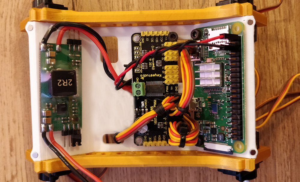
[Step 4] Wire everything
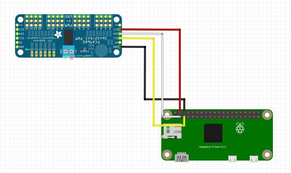
Connect the Driver board to the Raspberry Pi Zero
red: VCC +5V
black: GND
White: SDA
Yellow: SCL
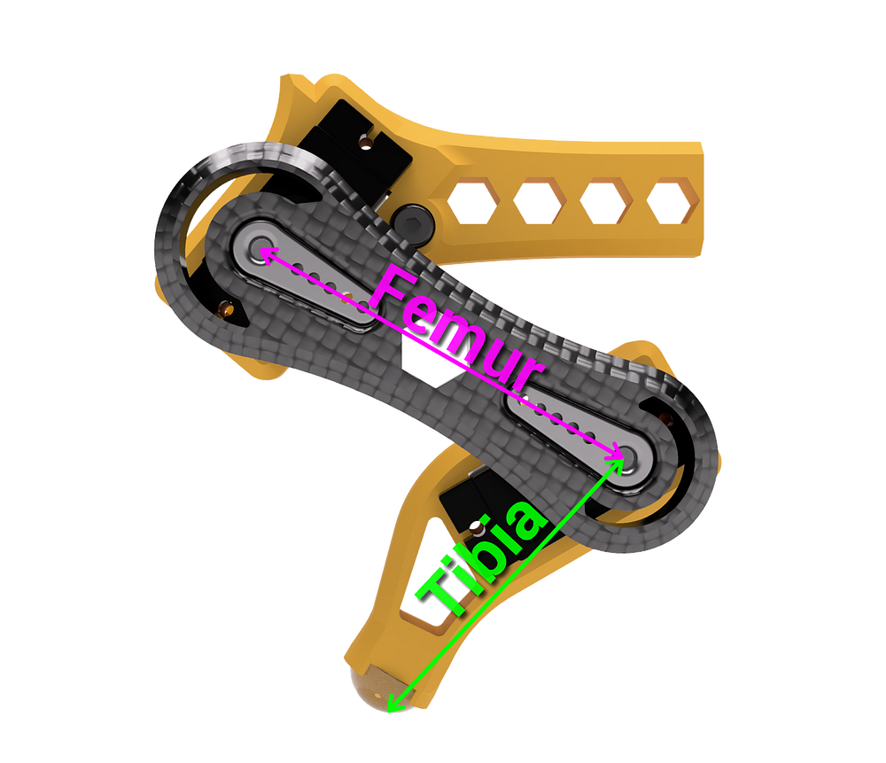
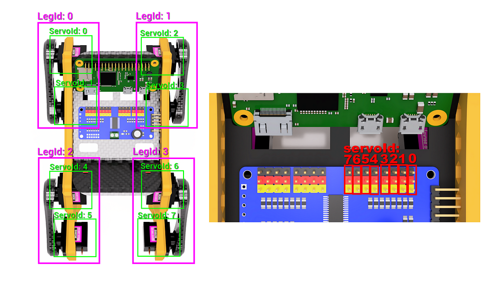
Connect all the motors to the driver, it’s important to adhering to the specified order below, from motors 0 to id 7. Ensure you use the left tibia on the left side of the robot and the right tibia on the right side.
Do not attach the legs to the motors yet, it’s crucial to set servo motors to the correct angles before
[Step 5] Calibration of the legs
Damn, it’s already time to do our first boot !
For this step you can use a usb cable to power up the pi or the battery as you wish, Just do not plug both at the same time please 🙃.
Once the Pi have fully botted it should be connect to your network automatically (Step 3/20)
Connect to the Robot via ssh with the following command:
Note: During the setup of the SD card, you specified a hostname and credentials for SSH; use them to connect to the robot.
ssh <yout-username>@<your-hostname>
e.g.
ssh pi@raspberrypi
Update the pi and reboot
sudo apt-get update
sudo apt-get upgrade
sudo reboot
Install all the requierments
sudo apt install build-essential
sudo apt install python3
sudo apt install python3-pip
- Enable the I2C Interface:
- Use
raspi-configto enable the I2C interface:
sudo raspi-config
Navigate to the Interfacing Options > I2C and enable it.
Install I2C Tools (optional but helpful for debugging):
sudo apt-get install -y i2c-tools
3. After installation, you can check which devices are on your I2C bus using:
i2cdetect -y 1